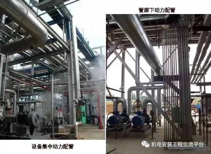
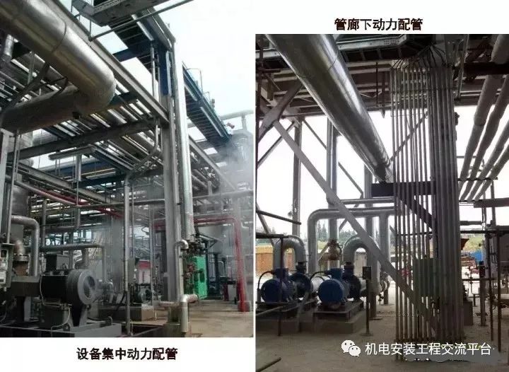
Source: if there is any infringement on the communication platform of mechanical and electrical installation engineering, please contact to delete the power embedded: cable protection tube (three cases): crossing protection tube; leading out from the cable trench to the equipment; leading out from the cable tray to the equipment
. 
Technical requirements: road crossing pipe construction: both ends of the cable pipe extend 2m from both sides of the road subgrade and 0.5m from the drainage ditch; cable protection pipe from the cable ditch: the drainage slope of the cable pipe is not less than 0.1%
. 
The side of the cable trench shall be well welded with protective grounding, and attention shall be paid to the coordination with the construction of the cable trench; during the construction, the layout of the electrical equipment and the wiring position of the equipment shall be found accurately
.
Generally, the motor faces the fan end and the inlet is on the left side
.
The low-voltage motor inlet is at the first anchor bolt of the pump foundation, and the high-voltage motor inlet is at the second anchor bolt of the pump foundation
.
At the same time, there should be a certain distance from the foundation
.
The position of the cable protection pipe of the motor with the same specification shall be consistent, and the cable control pipe shall be arranged in order
.
The bending radius of the buried cable protection pipe shall not be less than 10 times of its diameter
.
When the bending radius of the cable is required, the construction shall be carried out according to the bending radius of the cable
.
When cables enter buildings, tunnels and pass through floors and walls, protective pipes shall be used
.
Construction shall be carried out at the same time with civil engineering, and attention shall be paid to no omission
.
The prefabricated protective pipe shall be threaded with iron wire, and the pipe orifice shall be sealed by spot welding with rags or small iron plate
.
It is forbidden to use wooden plug
.
The trench shall be excavated according to the specified depth, backfilled and tamped layer by layer, and the protection work shall be done well, so as not to be damaged by the civil construction, and the marks shall be made
.
After the cable is laid, the protective pipe orifice shall be sealed to prevent the groundwater from entering into the cable
.
Sign and confirm the records of concealed works; pay attention to protect the cable pipe when laying the ground in civil engineering, and timely straighten the damaged one
.
When the conditions are met, the end of the cable pipe shall be cut off by gas welding, and the bell mouth shall be made
.
Cable tray: be familiar with the drawings, master the plane layout and elevation of the cable tray, and check whether there is any conflict between the cable tray and the process equipment and pipeline
.
According to the plane layout of the bridge, the elevation of each floor and the central coordinates of the bridge in and out of the building, the positioning and marking are carried out
.
The material shall be straightened and straight during the fabrication of column and bracket, the blanking error shall be within 5mm, and there shall be no curling and burr at the incision
.
The fabricated support is firm, flat, accurate in size, and painted with anti-corrosion paint
.
When the column and bracket are fixed on the metal structure or the building with embedded parts, they shall be fixed by welding
.
The welding shall be firm without significant deformation, and the welding shall be treated with anti-corrosion treatment
.
The components directly fixed on the concrete are installed with M12 expansion bolts
.
The distance between metal supports or brackets of cable tray installed horizontally meets the requirements of design and manufacturer’s installation instructions
.
The spacing can be appropriately reduced at the corner, terminal and other important positions; the reinforced support can be added at the bend and tee according to the design or bridge sample
.
In the installation procedure of cable tray, the elbow and tee are positioned first, and then the straight section is installed
.
Some parts need to be machined are cut and drilled by machine
.
The fabricated bridge is smooth and smooth without burr
.
The cutting and welding parts of galvanized materials shall be sprayed with zinc rich paint
.
Attention shall be paid to the surface derusting before spraying
.
The bridge is firmly fixed on each support and hanger, the internal and external connecting plates of the bridge are complete, the bolts of the connecting plate are fastened, and the nuts are located on the outside of the bridge
.
Appropriate expansion gap is reserved at the bridge interface, generally 30mm gap is reserved every 30m
.
Due to the limitation of space conditions, it is not easy to install the elbow or when there are special requirements, the hinged plate connection can be selected
.
The cable tray has reliable electrical connection and grounding
.
There is a grounding point every 30 meters
.
The main line and main line, main line and branch, branch and branch disconnection position of the cable tray must be crossed with the grounding wire
.
If there is no grounding jumper design at the cable tray connection, at least two spring washers can be added on the connecting bolts at both ends of each connecting plate as the grounding connection form
.
There is a certain slope from the inside to the outside when the cable tray enters the substation to prevent rainwater from flowing into the substation; exception: the construction of special material cable tray (such as aluminum magnesium alloy, glass fiber reinforced plastic, etc.) shall meet the special technical requirements (such as adding rubber pad between aluminum magnesium alloy tray and metal structure, repairing by the manufacturer of glass fiber reinforced plastic damaged parts, etc.) on-site electrical equipment installation: distribution box, power socket installation Installation: the installation and positioning of the distribution box and power socket shall be based on the requirements of the design plan, and the position shall not be moved at will; when the distribution box and power socket are installed on the steel column of the frame, the gap of the fireproof layer shall be left
.
The installation elevation of the distribution box and power socket shall meet the design requirements, and the verticality deviation shall not exceed 1.5 ‰
.
During the installation of the lighting box, attention shall be paid to the protection of the switch handle and monitoring instrument on the lighting box
.
The cables shall be connected in strict accordance with the phase sequence, especially the position of the grounding wire shall not be misplaced, the cables and plugs shall be well sealed, and no rain or water leakage shall be allowed
.
Installation of operation column: the position of the motor operation column shall be determined in strict accordance with the design requirements and the surrounding environment of the site, and the operation column with the same motor position shall be vertically and horizontally
.
The fixed height of the operation column meets the design requirements, the fixation is firm, and the verticality meets the specification; the direction of the button is easy to operate
.
Electrical connection between button and column, column and grounding grid is good
.
Power pipe surface matching: the steel pipe shall not have flat and cracks, and there shall be no iron filings, burr or other debris in the pipe
.
The cutting surface is smooth and the inner edge of the pipe is smooth
.
It is strictly forbidden to cut by electric and gas welding; when using the threading machine, the thread is required to be formed twice
.
After threading, clean the pipe orifice immediately to keep the pipe orifice smooth so as not to scratch the cable
.
The bending angle of the pipe is generally not more than 90 degrees
.
The bending radius of the exposed piping shall not be less than 6 times of the pipe diameter; if the bending radius of the cable is required, it shall be processed according to the bending radius of the cable
.
The bending radius of the same type of pipe should be consistent
.
When the cable is led down from the bridge, if the ladder is used, the pipe orifice of the cable pipe shall extend below the ladder
.
If the tray is used, if it is only a small cable, the protective tube can be fitted into the tray from the side, the steel pipe can be threaded, the two sides can be tightened with lock nuts, and then the protective mouth can be put on; if there is a large cable, the protective tube fitted into the tray can not meet the bending radius of the cable, the hole can be opened on the tray, and the protective tube is fitted under the tray
.
The piping mode of the same device shall be consistent
.
Whether the cable pipes are laid along the pipe gallery, platform or wall, they shall be arranged in order, and the fixed points shall be uniform
.
The pipes shall be fixed on the supports with pipe clamps, and the distance shall not exceed 3M
.
The allowable deviation of horizontal or vertical installation is 1.5mm/m, and the total length deviation is not more than 1 / 2 of the inner diameter of the pipe
.
If the pipe is connected by thread, the thread length at the pipe end shall not be less than 1 / 2 of the length of the pipe joint; after connection, the thread shall be exposed by 2-3 threads
.
Apply electric compound grease on the thread connection
.
The explosion-proof area must be connected with explosion-proof pipe fittings; the protective pipe leading to the equipment shall not hinder the disassembly of the equipment
.
The pipe orifice shall be fixed
.
If explosion-proof flexible pipe is required to connect with the equipment, the pipe orifice shall be threaded
.
The explosion-proof flexible pipe shall be free of crack, tear hole, mechanical damage, deformation and other defects, and the explosion-proof signs shall be complete
.
The pipe orifices at both ends of the protective tube need to be sealed
.
First, plug the cable tightly with non combustible fiber, and then fill with sealing mastic
.
The depth of sealing mastic shall not be less than the inner diameter of the tube, and shall not be less than 40mm
.
In addition to the design requirements, the electrical continuity between galvanized steel pipes installed along the earth, wood and stone structures must be maintained
.
If the installation needs to be disconnected, the grounding wires must be crossed between the pipe sections and reliably connected with the grounding system
.
Minimum distance between electrical circuit and pipe (mm) Note: ① for steam pipe, when the pipe is covered with thermal insulation layer, the parallel distance between upper and lower parts can be reduced to 200 mm
.
② Heat insulation layer shall be set for heating pipe and hot water pipe
.
Cable laying: preliminary preparation: be familiar with the drawings, check whether the cable tray, cable trench, bracket and cable protection pipe are connected in the whole process along the cable laying path, whether there are obstructions, and be familiar with the equipment tag number and plane position of each unit area; set up the scaffold and laying channel for high-altitude operation; number the cable reel transported to the site.
.


