Building Classification: it is generally considered that the house is composed of foundation or basement, wall, or column, beam, floor and ground, stairs and vertical traffic facilities, roof, door and window and other structural components
. 
1
. 
The purpose and content of construction engineering construction drawings are drawings showing the general layout of the project, the external shape, internal layout, structural structure, internal and external decoration, material practice, equipment, construction and other requirements of the building
. 
1
. 
Purpose (1) to guide construction (2) to prepare construction drawing budget (3) to arrange materials and equipment (4) to make non-standard components (2) contents (1) list of drawings (i.e
. 
the first page drawing) (2) general design description (3) architectural construction drawing (referred to as building construction) (4) structural construction drawing (referred to as structural construction) (5) equipment construction drawing (referred to as facilities) (2) design of architectural construction drawing Features 1
. 
The drawings in the construction drawings are mainly drawn by orthographic projection method
. 
2
. 
The drawing scale is small, and the unified legend or code is often used
. 
3
. 
Different contents in the construction drawings use different line types
. 
3、 1
. 
Be familiar with the functions of the proposed project
. 
Understand the type, basic composition and decoration of the project
.
2
.
Read the manual and catalogue carefully
.
Know how many types of drawings there are and how many sheets of each type
.
3
.
First the whole, then the part, first the building, then the structure, first the plane, then the facade
.
4
.
First icon, text, then pattern; first graphic, then size
.
Construction drawing identification method 1
.
Drawing catalog
.
The drawing catalog includes the name, content, drawing number of each drawing, indicating which professional drawings and which drawings the engineering drawing is composed of, so as to facilitate retrieval and search
.
2
.
General description of design general description of design mainly introduces the general situation and general requirements of the project
.
The contents generally reflect: 1) design basis (such as planning restrictions, design scale, building area and relevant geological and meteorological data, etc.)
.
2) Design standards (such as building standards, structural load levels, seismic requirements, etc.)
.
3) Construction requirements (such as construction technology, material requirements and process description of new technology, new material or special construction)
.
3
.
The general plan of a building is a drawing that represents the general layout of a building site
.
In the form of plan, it shows the terrain, features, roads, the location and orientation of the proposed house, and the relationship with the surrounding buildings
.
Due to the small scale of the drawing, the houses and various ground features and building facilities can not be drawn according to the real horizontal projection, but for schematic expression
.
1) Look at the title, scale, legend and related text
.
2) Understand the land use scope, topography and surrounding environment of the project
.
3) Understand the plane position and positioning basis of the proposed house
.
4) Understand the orientation and main wind direction of the proposed house
.
5) Understand the road traffic and pipeline layout
.
6) Understand the requirements and layout of greening and beautification
.
4
.
Building plan the building plan shows the plane condition and layout of the building, including the division of rooms, the layout of stairs and aisles, the layout of wall and column components and axis number, the location of doors and windows, the plane size, the layout of sanitary facilities, etc
.
The building plan includes the following contents: 1) positioning axis
.
All bearing walls and columns must be marked with positioning axis and numbered in sequence
.
2) The outline line of wall and column section cut to the drawing line shall be drawn with thick solid line, and the visible outline line not cut to the drawing line shall be drawn with medium solid line
.
The dimension line, boundary line, leading line, legend line, index symbol and elevation symbol are drawn with thin solid line, and the axis is drawn with thin single point long line
.
3) Scale and legend plans are usually drawn at the scale of 1:50, 1:100 and 1:200
.
4) Generally, the cutting position line and projection direction of the section shall be marked in the bottom floor plan, and the number shall be marked; for the components, fittings and nodes that are represented by standard atlas or other detailed drawings, the detailed drawing index symbol shall be drawn for reference
.
5) The dimension of the plan includes: external dimension and internal dimension (1) external dimension: mark three dimensions on the outside of the outer wall
.
The first (outermost) dimension: the overall dimension of the outer contour of the house, that is, the total length and width from one end of the outer wall to the other
.
It can be used to calculate building area and floor area
.
The second (middle one) dimension: the dimension between the positioning axes of the house
.
Generally, the dimension between the transverse axes is the Bay dimension, and the dimension between the longitudinal axes is the depth dimension
.
The third (innermost) dimension: segment dimension, indicating the width and position of door and window openings, wall stack segment and detail structure, etc
.
2) Internal dimension: all dimensions within the external wall, mainly used to indicate the location and width of the door and window openings of the internal wall, the thickness of the wall, the location and size of fixed equipment such as sanitary ware, stove and wash basin
.
In addition, it should also indicate the relative elevation of the building and the ground, as well as the name of the room and the number of doors and windows
.
Read the building plan: 1) understand the title, scale and text description
.
2) Understand the vertical and horizontal positioning axis and number
.
3) Understand the plan shape and overall size of the house
.
4) Understand the layout, use and transportation of the room
.
5) Understand the layout, quantity and model of doors and windows
.
6) Understand the room, depth, detail size and indoor and outdoor elevation of the house
.
7) Understand the details of the building structure and equipment configuration
.
8) Understand the cutting position and index symbol
.
5
.
The elevation of the building reflects the appearance of the building, and the indoor structure and facilities are not drawn
.
Due to the small scale of the drawing, the details of doors, windows and buildings can not be shown in detail
.
The basic outline of the drawing is only drawn, or it is indicated by the specified legend
.
It is used to reflect the level change and artistic effect of the building facade, and provide the basis for the shape design and later decoration of the building
.
Read the building elevation: 1) look at the title, axis and scale to understand which elevation it represents
.
2) Look at the outdoor floor elevation, understand the indoor and outdoor height difference, and check the number of outdoor steps
.
3) Understand the form and location of doors and windows, balcony, awning, steps, roof, plinth and other details
.
4) Check the elevation of each part, understand the indoor and outdoor height difference, floor height, total building height, canopy, windowsill height, etc
.
5) Understand facade decoration materials, colors, etc
.
from explanatory text or index symbols
.
6) Understand the location of rainwater pipes and check with the roof plan
.
6
.
The building section mainly shows the internal structure of the house, the stratification, the height of each floor, the structure of the floor and the ground, and the relationship between the accessories in the vertical direction
.
The cutting position of the section should be selected at the position that can reflect the internal structure, and can pass through the door and window openings and staircases
.
The projection direction and view name of the section shall be consistent with the annotation on the plan
.
Read the building section: 1) understand the title and scale of the drawing
.
2) Understand the corresponding relationship between section and plan
.
3) Understand the structure of the house
.
4) Understand the main elevation and dimensions
.
5) Understand the structural levels and practices of roof, floor and floor
.
6) Understand the roof drainage method
.
7) Understand the location and number of the detail index
.
7
.
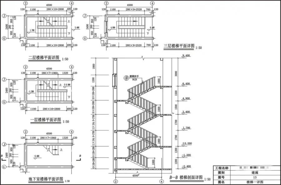
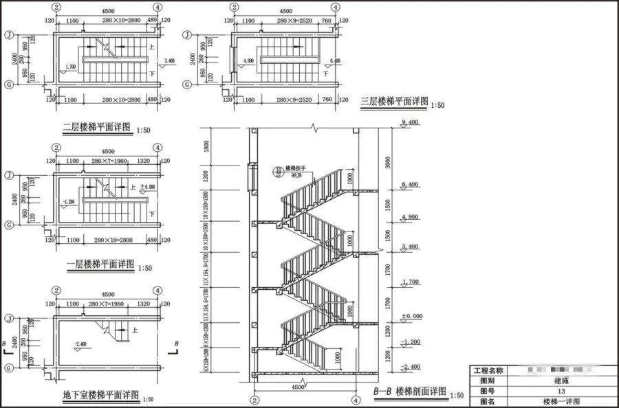
The plan, elevation and section of the building detail reflect the whole picture of the house, but due to the small scale of the drawing, the structure, method and materials of some details can not be expressed clearly directly
.
In order to meet the needs of construction, these parts need to be drawn separately with a larger scale, which is called the building detail
.
Building details are the construction drawings of building details, the deepening and supplement of basic drawings such as building plan, elevation and section, and the basis of detailed construction of building engineering, the production of building components and the preparation of budget.
.


